
DFM analysis reduces the risk of errors during production
DFM analysis (Design for Manufacturing) is a key process that significantly improves the production efficiency and reliability of manufactured equipment. As part of this, engineers optimise the design so that it is quicker, easier and less costly to manufacture the equipment.
Is it possible to avoid production errors that shorten product life, increase costs unnecessarily or extend delivery times?
How can production costs be reduced without sacrificing device quality?
A Design for Manufacturing analysis is a specialized review of a design by the Process Technology Department. Its task is to rule out not only possible errors in the design, but also to identify solutions that may unnecessarily complicate the production process; both of which may significantly increase costs or have a negative impact on the ability to ensure product quality or extend lead times. The procedure is fully adapted to the specific customer’s needs. It ensures that the design is not only tailored to structural or performance requirements, but also considers the specific requirements of the contract manufacturer. For this reason, it is advisable to carry out a DFM analysis at the earliest possible stage.
- Meeting technical and functional requirements : The product design should meet all technical and functional requirements, ensuring optimal performance and quality in the production process.
- Simplifying the design: Avoiding complex designs that can lead to production problems and additional costs.
- Minimising the number of parts: Reducing the number of product components helps reduce assembly complexity and the risk of production errors.
- Use of standard parts: The use of standard components cuts the cost of implementation into production and facilitates the sourcing of materials.
- Optimisation of the distance between components on the PCB: Prevents component misalignment, thus reducing the risk of production stops and costly rework.
- Ensuring material availability: Selecting materials that are easily available on the market can reduce delivery times and costs.
- Ensuring ease of assembly: The design shall take into account ease of assembly to reduce the time required for operations in the assembly process.
- Preventing manufacturing problems: The DFM analysis is expected to include the identification of potential manufacturing problems and their elimination at the design phase.
- Selection of optimal manufacturing processes: Designing a product with optimised manufacturing processes in mind can help reduce production costs and times.
- Thoughtful use of technology: Selecting appropriate manufacturing technologies and assembly processes can have a significant impact on the productivity and quality of the finished product.
We carry out an assessment of ‘`mountability’ when quoting. Engineers from the Process Technology Department analyse the project and identify potential technological problems originating from the design. Thereafter, they inform the customer how the problem can be solved. Since this process aligns with the pricing, it does not impact on the timing of the project.
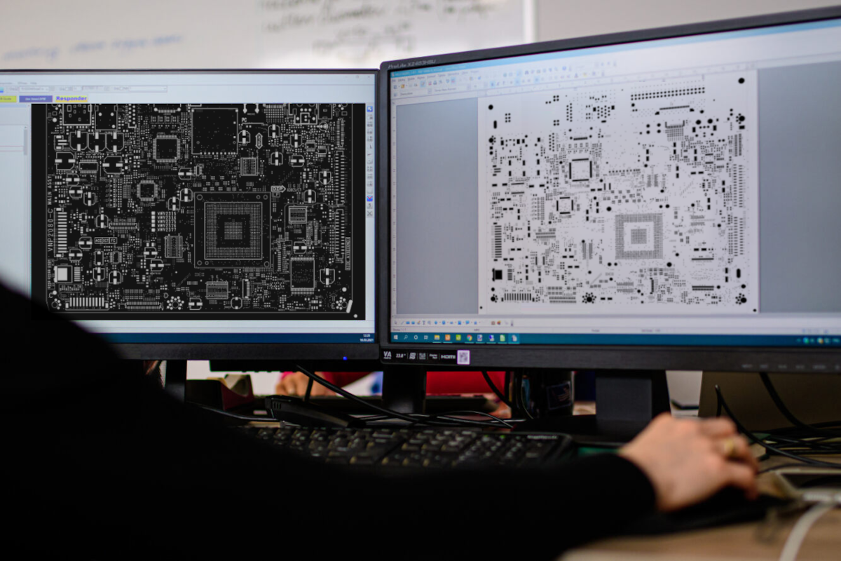
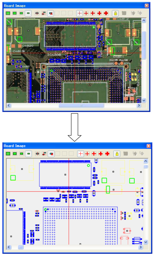
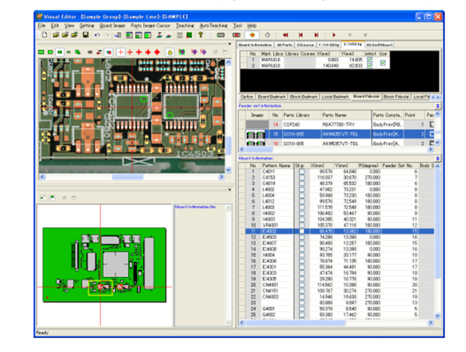
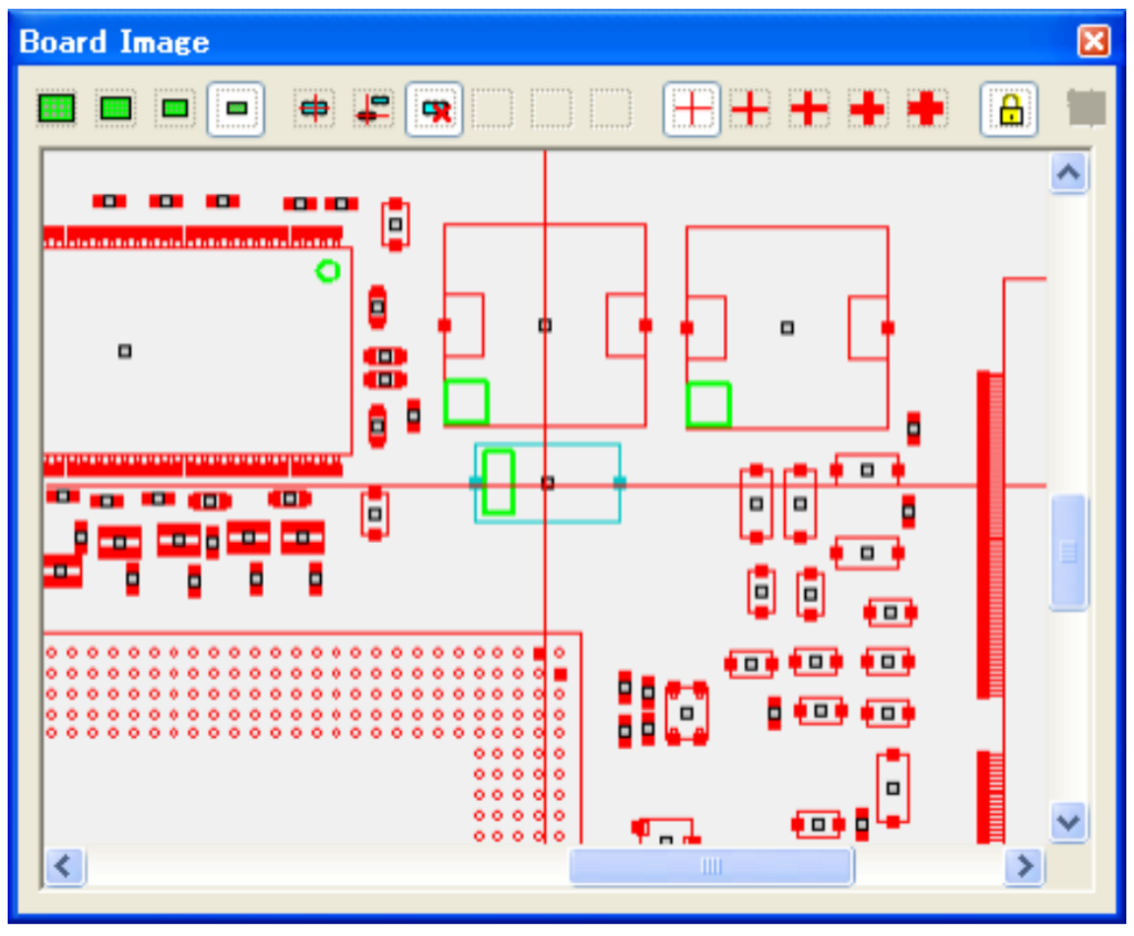
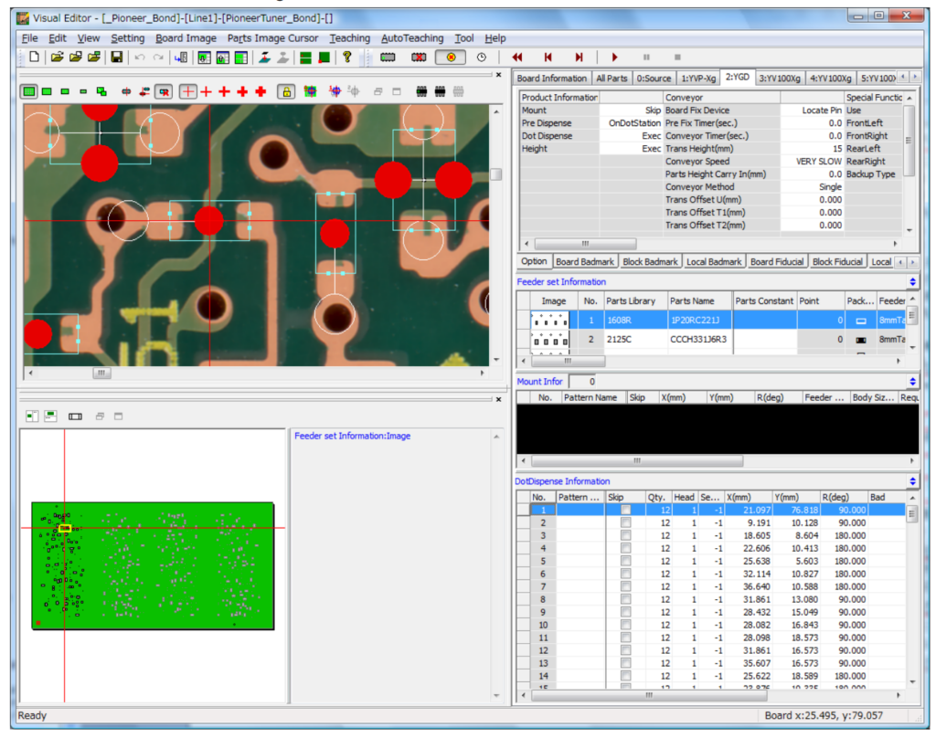
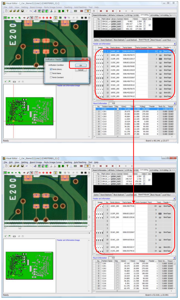
Before starting SMD assembly, we carry out a further analysis using an advanced simulation tool that interacts with our p&p machines, a tool we are the few in Poland to use. The software is used to program the production machines and allows us to see the generated view of the components on the PCB image. The tool outputs models of the components with realistic dimensions; in this way we can see with a high degree of precision, also in zoom, whether all the components correspond to the anticipated layout. This is particularly important in cases with high component density or extremely small component sizes. In addition, we can also add our own components to the existing component library – the scanner will take a photo and accurately describe the component model on the basis of this.
By using this boosting tool, we can avoid a situation where a failure is detected during assembly. In such a case, production would have to be stopped, which would burden both the customer and the EMS manufacturer with high costs and delays.
Expertise allows for better results. Our engineers have a unique know-how, developed as a result of more than twenty years in the industry and the analysis of hundreds of different PCBA projects. Their knowledge is not only limited to theoretical principles, but also includes practical knowledge developed during the preparation and planning of production processes. Combining the experience of the engineers in your teams with that of our Process Technology Department creates added value, contributing to the quality of the final products.
First of all, we categorise engineers’ insights according to the rank of their importance.
It sometimes happens that a very significant non-conformity is found in the design. If this is detected too late, i.e. after the production process, the resulting defects have to be corrected manually, which significantly prolongs the process and increases costs. A common case is also an error in the BOM, for example containing an unsuitable equivalent for an unavailable component or an incorrect identification. An example would be SO8 and SO8W components that differ in size; an oversight will result in the wrong size component not being able to be soldered correctly, so this must be prevented before the manufacturing process. An faulty design can also make it impossible to work in accordance with the IPC standard describing assembly correctness.
As professionals with more than 20 years’ experience, we have a practical knowledge of assembly principles and have therefore developed rules that allow us to optimise the production processes. For example, it is sometimes the case that moving a component by literally millimetres will make it possible to rule out manual soldering completely, which is a relatively expensive operation. Changes that allow wave soldering are also the most efficient – because whether there are 2 leads or 200 leads in the design, the process takes the same time. It is also important to decrease the number of PCB sides to be assembled as an option; for example, some components, due to their specifics, should enter the reflow oven only once in order not to lose their properties, so it is worth identifying all such components and placing them on one side of the board. It is worth noting that in some cases double-sided assembly can be avoided entirely.
Every design change that is preceded by an analysis, if possible, means a great deal of simplification for the manufacturer and benefits the client. If a mistake can be detected earlier, there will be no need for rework, which takes time and costs money, especially if it requires manual intervention by assemblers. Moving components by a millimetre, or repositioning individual components, can allow the number of processes to be reduced or replaced by more efficient ones. The initial design may require manual soldering, but better efficiency, quality and repeatability can be achieved by using selective soldering. The final method is wave soldering, which retains all the advantages of selective soldering plus the production process takes less time, reducing lead time as well as the cost of the job. Thus, a timely design change can only allow the use of the latter, the least costly and fastest way, while maintaining the full functionality and quality of the final product.
The analysis is not only about the layout of the components on the PCB, but also about the PCB itself. The design, for example, due to the distances between pads, may require the use of a more expensive PCB manufacturing technology. Redesigning the device in consultation with our Process Technology Department will reduce costs in this area as well, by enabling the use of a less expensive PCB fabrication technology.
Introducing changes that reduce the number of processes always means reducing costs and production times, so it is worthwhile for customers to benefit from the comments made by our experts.
Reducing production costs has a significant impact on the price of the final device, giving you an important competitive advantage. Reducing production time means that the final device can be brought to market earlier. And, in addition, the end product is of better quality, thus minimising the risk of complaints or negative feedback from your customers. DFM analysis is therefore not just a routine procedure.
JM elektronik have assembled millions of devices, both simple and complex, during our more than 20 years of operation in the EMS industry. We are sometimes asked by customers to check their designs or prepare a PCB revision. We are here to help – the analysis prepared by the Process Technology Department helps to detect significant bugs and also to improve the production process.
We have been in long-term partnership with many customers. Companies pleased with our services contract us to manufacture the next generation of their equipment. We have also worked together on many occasions, providing feedback to improve their assembly or reduce the total cost. Thanks to long-term cooperation, customers can enjoy not only a trusted supplier, but also the opportunity to reduce unnecessary costs through the experience sharing between the customer and the EMS teams.
We constantly search for superior technology and more cost-effective solutions. We feel responsible for your brand, so quality is our main criterion. Fill in the contact form and see how we can assist you.


