
In-Circuit Test – why can it usually be a more beneficial choice than the Flying Probe test?
In electronic manufacturing, quality control is very important. Two widely used methods for testing printed circuit board assemblies (PCBAs) are the In-Circuit Test (ICT) and the Flying Probe Test (FPT). Both techniques are used to identify defects and ensure correct functionality of assembled boards. Each method has its own unique strengths and limitations, making it crucial to understand their differences and suitability for different PCBA applications.
This comprehensive article discusses the details of ICT and FPT, exploring their operational rules, advantages, disadvantages and practical applications. After reading this article, the readers will know which testing method is best suited to their PCBA assembly needs. This will enable you to make conscious decisions that optimise quality, performance and cost-effectiveness.
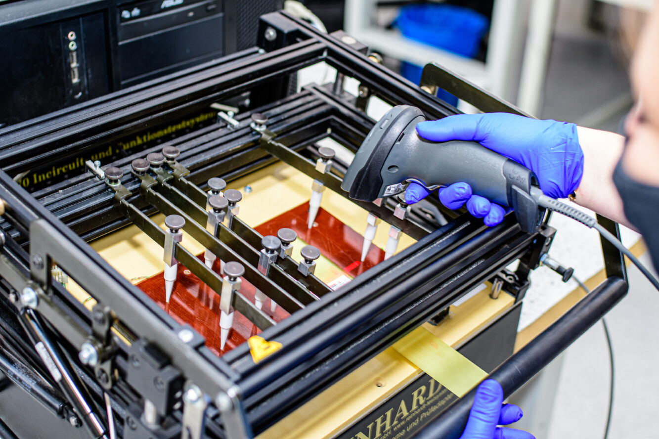
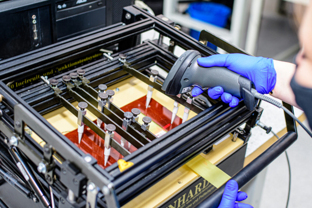
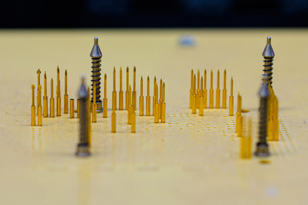
In-Circuit Test (ICT) is an electrical test method that verifies the functionality and integrity of individual components of a printed circuit board assembly (PCBA). It is a test method that involves placing the PCBA on a holder with numerous spring-loaded test probes (needles) that physically contact specific test points on the board.
During the ICT process, test probes are lowered onto the PCBA, making electrical connections to designated test points. Then, a specialised test programme applies a series of electrical signals and measurements to verify the correct operation of each component, including resistors, capacitors, ICs and connections.
The ICT system compares the measured values with predefined expected values or ranges, enabling the detection of faults such as:
- open circuits
- short circuits
- deviations in component values
- incorrect component orientation
- solder bridges
- missing components
High test coverage: ICT provides comprehensive testing capabilities by verifying individual components and their interconnections. This ensures precise quality control and error detection.
Efficient testing: Once the test fixture and programme are configured, ICT can quickly and efficiently test multiple boards in a production series, reducing overall test time and increasing capacity.
Early defect detection: ICT can identify defects early in the production process, before further assembly steps are taken. This helps prevent additional resources being wasted on faulty boards and facilitates timely corrective action.
Repeatability and consistency: ICT tests are highly repeatable and consistent as they follow predefined test programmes and use dedicated test instrumentation. This ensures reliable and replicable test results across multiple boards.
Limited access: ICT requires direct physical access to test points on the PCBA board, which can be difficult on densely packed boards or boards with components on both sides. Some test points may not be accessible, leading to reduced test coverage.
Instrumentation creation: creating dedicated test fixtures for each PCBA project can be time-consuming and costly, especially for low-volume or prototype boards. The fixture must be precisely designed and manufactured to ensure accurate probe placement.
Fixture constraints: the test fixture may impose limitations on the size and complexity of the PCBAs that can be tested. Large or irregular boards may not fit or be compatible with the fixture design.
Test point damage: physical contact between test probes and PCBA test points can cause damage or wear over time, especially with fine-pitch components or fragile pads.
Flying Probe Test (FPT), also known as Grid Test or Probot Test, is a non-contact method of electrical testing of printed circuit board assemblies (PCBAs). Instead of using a dedicated test instrument, FPT uses a set of moving test probes that move across the surface of the PCBA, taking electrical measurements at designated test points.
In an FPT system, a PCBA board is securely mounted on a test surface, usually on a vacuum table or chuck with mechanical clamps. Two or more test probes, controlled by precise motion systems (such as robotic arms or linear motors), are moved across the board surface to access the desired test points.
Test probes make temporary electrical connections to test points, enabling the system to perform various electrical tests and measurements. These tests can include:
- component verification
- continuity testing
- resistance measurements
- capacitance measurements
- functional tests (with additional instrumentation)
The test sequence and expected values are defined in the software, which directs the movement of the probes and compares the measured values with predefined tolerances or specifications.
Instrumentation-free testing: FPT does not require dedicated test instrumentation for each project, eliminating the need to develop ficstures. This makes it very flexible and improves the testing process for prototypes and small production runs. However, it should be noted that it requires the purchase of expensive test equipment, which requires the preparation of complex FP test run programmes for each product.
Accessibility: movable test probes can access almost any test point on a PCBA, including dense areas and components on both sides of the board. This ensures excellent test coverage, even for complex and irregular PCBA shapes.
Adaptability: FPT systems can be easily reconfigured or reprogrammed to adjust to new PCBA designs or test requirements. This adaptability makes them well suited to rapidly changing production environments and frequent design iterations.
Capacity limitations: FPT for large production runs is several times slower because the moving probes have to move and make individual connections at each test point. This procedure significantly increases the total test time per board. Due to the high cost of probes, companies rarely decide to purchase additional test probes, so that the testing process can become a bottleneck for large production runs.
Programming complexity: developing and validating test programmes for FPT can be more complex compared to ICT, as probe movements and test sequences must be precisely defined for each PCBA design.
Wear and maintenance of probes: repeated contact between test probes and the PCBA surface can lead to probe wear and potential contamination over time. Regular maintenance and replacement of probes may be required to ensure accurate and reliable test results.
Test environment requirements: FPT systems often require a controlled and stable test environment to minimise the impact of external factors such as vibration or electromagnetic interference on high-precision probe movements and measurements.
In-circuit Test (ICT) is usually the preferred choice in the following scenarios:
High-volume production: for large production series of a specific PCBA design, ICT offers efficient and consistent testing capabilities, making it suitable for high-volume production environments.
Well-established product lines: when the PCBA design is well established and unlikely to change frequently, the initial investment in developing dedicated test fixtures can be justified by the long-term benefits of efficient and repeatable testing.
Functional testing requirements: while ICT focuses mainly on component-level testing, some systems can be integrated with additional instrumentation to perform limited functional testing of assembled boards.
Cost optimisation: in high-volume production scenarios, the initial cost of tooling development can be offset by lower operating costs and higher ICT capacity, making it a more cost-effective solution over time.
Flying Probe Test (FPT) is often the preferred choice in the following scenarios:
Prototyping and small-volume production: FPT’s fidgetless and needle bed approach and programming flexibility make it well suited to prototype development, small production runs and frequent design changes.
Complex or irregular PCBA designs: FPT can access test points on dense or irregular shaped boards.
The characteristics of both testing methods define in which situations they can be used most effectively. In our experience, clients usually choose the ICT method because of the sum of the benefits, which are better suited to the needs of the projects that most often come to us. FPT technology is mainly used for particularly complex, prototype and low-volume projects, which makes it less common and less frequently chosen despite its attractiveness.


