
How to Choose Soldering Technology in EMS? A Practical Guide for R&D and Purchasing Teams
The selection of soldering technology in EMS is rarely a purely technical decision. In practice, it is one of those moments where engineering meets business: this choice directly affects device reliability, unit cost, production scalability, and the risk of service issues throughout the product life cycle.
In modern contract manufacturing, there is no single “best” soldering method. Instead, there is a combination of technologies that is optimal for a specific project – its BOM, PCB geometry, component sensitivity, and planned volumes.
Below, we show how EMS providers approach the selection of soldering technology in practice and when a given method truly makes business sense.
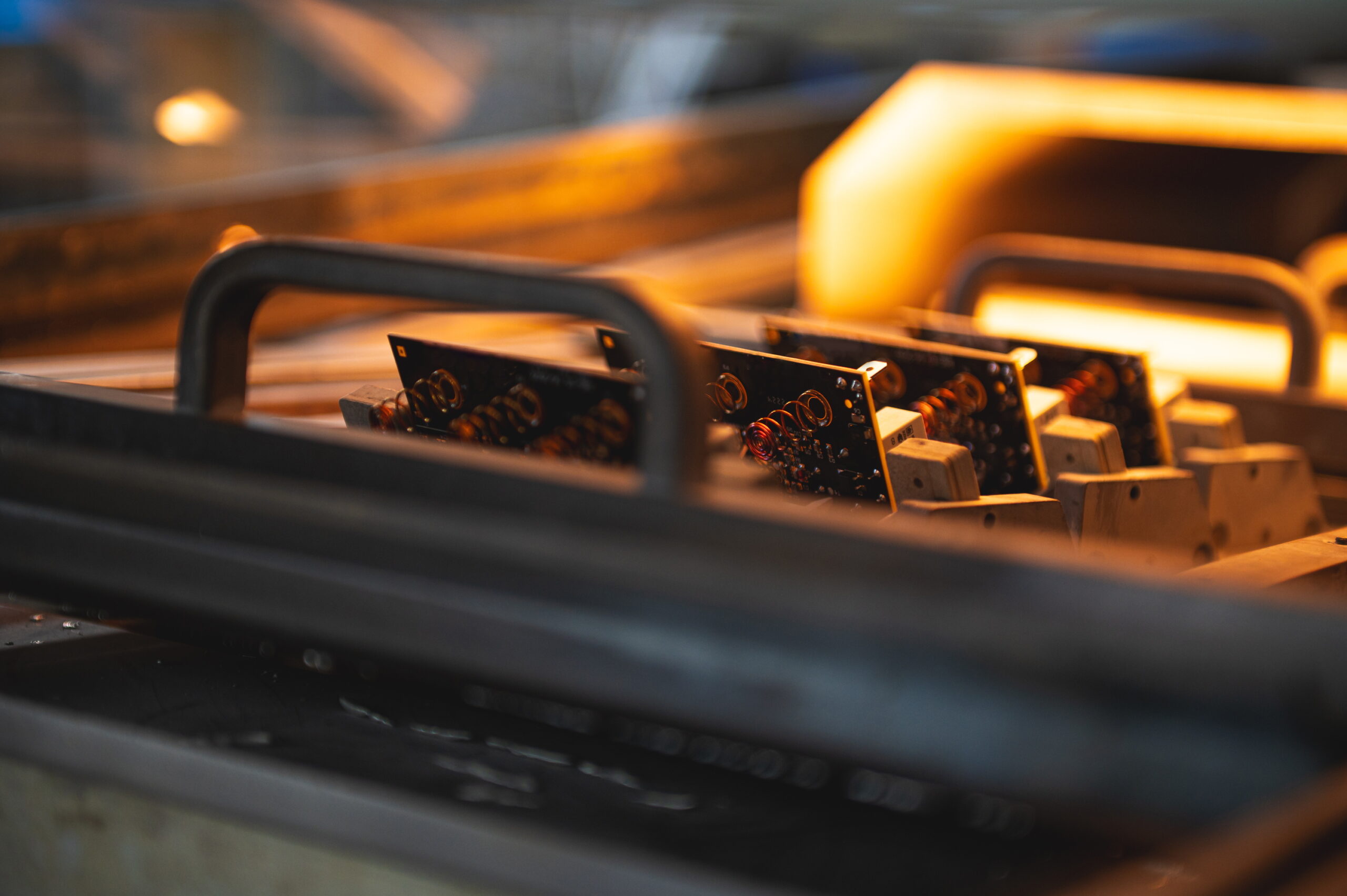
Reflow Soldering
Reflow soldering is today the foundation of SMT assembly. A board with applied solder paste passes through an oven with a controlled temperature profile – from preheating, through flux activation, to the reflow phase and controlled cooling. This technology scales well for both prototypes and series production, provided the profile is correctly matched to the thermal mass of the PCB and the types of components used.
Reflow makes the most sense where SMT components dominate, volume scalability is planned, and the design includes packages such as BGA, QFN, or SiP modules. With a well-designed PCB, it delivers high repeatability and stable quality.
However, it is not the optimal choice for boards with highly uneven thermal mass, extremely thermally sensitive components, or prototype designs in which the layout changes from iteration to iteration. In such cases, problems such as tombstoning, voiding, or component shifting usually result not from the technology itself, but from improper profile engineering and PCB design.
In EMS practice, reflow issues more often stem from an incorrect thermal profile than from the technology itself.
Low-temperature soldering uses alloys with melting points in the range of 138–175°C instead of the classic SAC305. Its main advantage is reduced thermal stress, which is important for thin laminates, dense modules, and sensitive BGA packages.
LTS can be highly effective in high-density designs and where a conventional reflow profile causes component deformation. At the same time, it is a technology with a narrow process window, sensitive to heating rates and time above liquidus.
It is not a safe choice for hybrid designs (mixing SAC and LTS), in situations with limited material availability, or in applications where joint mechanical strength is critical – for example, in devices exposed to vibration, shock, or intensive temperature cycling.
Low-temperature soldering can rescue thermally sensitive designs, but it is not a substitute for SAC305 in high-reliability applications.
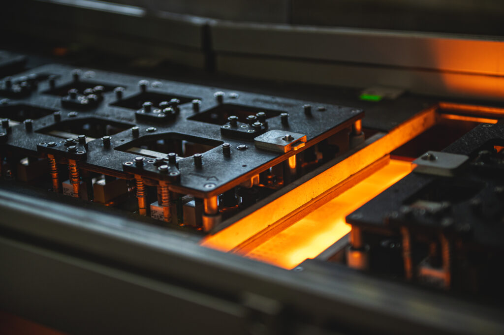
Wave soldering remains the basic technology for assembling through-hole components (THT) in series production. The PCB passes over a pot of molten solder, which simultaneously forms all joints. This solution is highly cost-effective for medium and large volumes.
Wave soldering works best in designs dominated by THT, with a stable layout and well-prepared DFM. Under these conditions, it ensures low unit costs and high repeatability.
Problems arise when attempting to use it for densely populated boards, double-sided SMT assemblies, or projects with high design variability. The lack of pallets, large mechanical tolerances of connectors, and mismatched PCB geometry lead to bridging and unstable joints. In such cases, instead of helping, wave soldering generates defects.
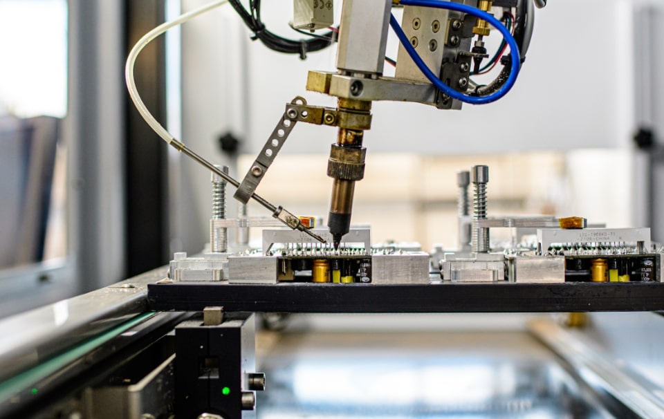
Selective soldering uses a mini-wave and precise flux application for point soldering of selected THT components. This technology is designed for mixed SMT + THT boards and High-Mix Low-Volume environments.
Selective THT provides much greater quality control than wave soldering and allows only those components that require it to be soldered. It works well where the volume is too high for manual assembly but too low or too variable for classic wave soldering.
However, it is not optimal for very large volumes or where cycle time is absolutely critical. In such cases, wave soldering remains the more economical solution.
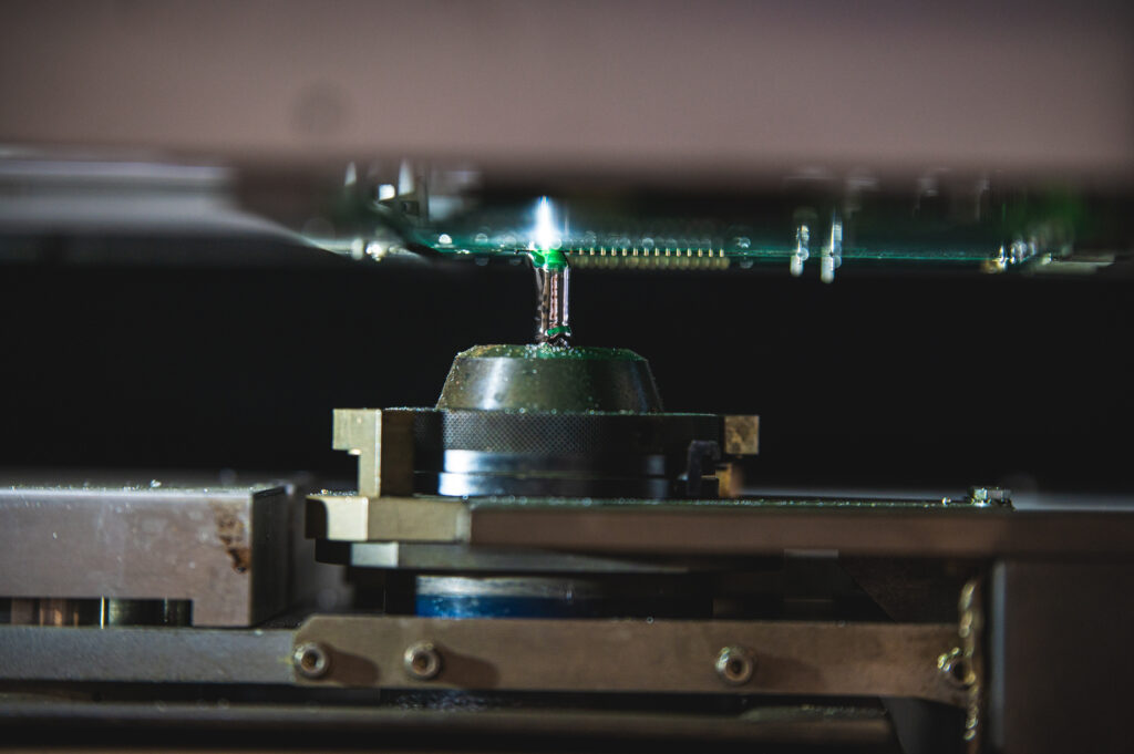
A soldering robot is a station for point THT soldering, in which the soldering head is numerically controlled along the XYZ axes. It allows precise control of temperature, contact time, and solder amount for individual solder joints.
In practice, a soldering robot makes sense in EMS for short but repeatable series after the NPI stage, when the design is already preliminarily stabilised and the quality of manual soldering begins to vary between operators. It is also useful for hard-to-reach solder joints.
However, it is not the right choice for very small volumes, frequent PCB layout changes, or large mechanical tolerances of boards. The cost and time required for programming often exceed the time needed for manual soldering. With a larger number of THT points, the robot quickly becomes a bottleneck in the process.
In EMS, a soldering robot is not a volume solution, but a transitional tool between manual THT and selective mini-wave soldering.
Manual THT assembly is soldering performed by an experienced operator using a soldering station, flux, and solder wire, without full automation of the process.
In the Polish cost environment, manual soldering remains economically justified in many low-volume projects. It works particularly well for prototypes and NPI, for PCBs unsuitable for automation, for components with large mechanical tolerances, and where speed of response is critical – for example, for series of a few to a dozen units “needed yesterday”.
Of course, it has its limitations: quality depends on the operator’s experience, repeatability is lower than in automated processes, and scalability quickly diminishes as volumes increase.
In the Polish cost environment, manual THT soldering often provides a better cost–time–quality balance than partial automation.
Ultra-precision soldering is used for extreme miniaturisation – 01005, μBGA, QFN, microLED components, and SiP modules. It requires the use of Type 6 and Type 7 solder pastes and advanced SPI and AOI control.
This is an area with a very narrow process window, where the experience of process engineers, precise paste printing, and a stable reflow profile are critical. It enables extreme miniaturisation, but does not tolerate mistakes.
In EMS PCB assembly practice, most soldering problems do not result from “bad technology”, but from a mismatch between the technology and the project’s real requirements.
One of the most common cases is BGA joints cracking after several temperature cycles. Usually, the issue is not the component itself, but an overly aggressive reflow profile or the failure to use low-temperature soldering with thin laminates. In such designs, classic SAC305 is simply too thermally “hard”.
Another recurring problem is bridging and unstable joints in THT components. This is most often caused by attempting to force wave soldering on boards that were not designed for it. Dense component placement, large mechanical tolerances of connectors, or the lack of pallets mean that instead of helping, wave soldering generates defects. In such cases, manual THT or selective soldering produces a much better end result.
We also frequently encounter disproportionately high costs for very small NPI series. This happens when automation is launched for batches of only a few to a dozen units, requiring lengthy setup – programming a soldering robot or retooling a selective wave system. In the Polish cost environment, manual soldering is simply faster and cheaper in such projects.
A separate issue is low quality repeatability in short runs. Here, the problem is both manual soldering performed by different operators and switching to a soldering robot too early when the design is still unstable. In practice, a phased approach delivers the best results: manual THT at the NPI stage, a robot only after the layout has stabilised, and selective wave soldering when entering serial volumes.
Finally, many customers complain about long time-to-market when design changes occur. This is most often due to an overly rigid production process that requires reprogramming of automation each time. Maintaining manual and semi-automated THT as a flexibility buffer allows rapid response to design changes without blocking production.
The choice of soldering technology directly affects unit costs, product reliability in the field, the ability to scale production, and time to market.
That is why, in a professional EMS environment, the process always starts with an analysis of the BOM, PCB geometry, quality requirements, and planned volumes – not with the question, “What machine do we have on the shop floor?”
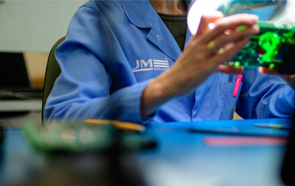
At JM elektronik, we treat the selection of soldering technology as a business decision, not a showcase of our machine park. Our goal is not to “automate everything”, but to find the right balance between cost, quality, flexibility, and scalability.
We start each project with an analysis of the BOM, PCB geometry, mechanical tolerances of components, thermal sensitivity of circuits, and planned volumes. The product life cycle is equally important – working with a prototype is very different from working with a mature product that returns every month in the same batch size.
In practice, we use reflow soldering as the basis for SMT assembly, wave soldering for serial projects dominated by THT, and selective mini-wave soldering for mixed SMT + THT boards. We also maintain manual THT assembly, which in the Polish cost environment remains a rational choice for NPI, prototypes, and “difficult” boards unsuitable for automation. We treat soldering robots as a transitional solution – between manual THT and selective wave soldering – used when the design is already preliminarily stabilised and the quality of manual soldering begins to fluctuate.
We do not offer vapour phase technology because, under Polish market conditions and typical EMS volumes, it is rarely economically justified. Instead, we optimise reflow profiles and, where appropriate, use low-temperature soldering for thermally sensitive components.
In practice, this means that we do not push automation where manual assembly offers a better cost–time–quality balance. For us, a well-chosen process is one that can be repeated in six months without changing the technology and without increasing unit costs.
This approach allows us to shorten time-to-market for NPI, reduce soldering defects in high-density designs, and enable customers to scale production without changing their EMS partner.
If your board combines SMT, THT, and thermally sensitive components, undergoes frequent design changes, or is to be produced in short, repeatable series, it likely requires a non-standard selection of soldering technology.
Contact us – we will analyse your project and propose a production process tailored to the cost and volume realities of your business before production begins.


